README of my Unity NavimeshMarker plugin
1. How it works
It is useful to bake meshes into a NavMesh file in Unity. As the project turns large, the meshes can be too complex to match a navigation area. And the longer I work with it, the stronger feelings I have would be if
- I can edit the navmesh freely within Unity. I have to select/un-select the existing mesh made by the artist, which is easy to make mistakes. If I want to mark certain areas, my jobs would probably depend on the artist.
- I have the open format runtime data so that I don’t have to re-bake it for my server. The re-baking workflow makes the server data different from the client’s, which brings in bugs.
So I make NavimeshMarker. NavimeshMarker is a Unity Editor tool that aims to
- be a navmesh editor within Unity. The user can easily generate and edit meshes sticking to the ground. With the meshes, it is easy to mark a certain area as a specific Navigation Area, which can have different navigation costs. Then a smarter navigation path will be generated at the runtime and leads to a better AI interaction with different terrains.
- provide a bake-free runtime navmesh data with Open Detour format.
After the meshes are generated, you can follow the old workflow to bake it to the navmesh data in the Unity Navigation Panel. And the navmesh data, instead of the meshes, is utilized at runtime eventually. And the meshes won’t be saved with the scene. Instead, they are saved as files in a directory besides the scene file. And it needn’t be packed into the game, which will save the memory at runtime.
Or you can also export the navmesh without the baking workflow. The meshes intersection and the union calculation will be performed(The source code of this part is in secret.) during the exportation and the edge vertices are kept. Then the data will be saved in JSON format and transferred to the Detour format. An example is provided to show how to use these data in Unity. And it can be used anywhere as it is written in C++. The exporting and the runtime source are available via this link(I only add new files and nothing changes are made to the original source, so it is easy to rebase.). In this workflow, you must pack the runtime data into the release package.
As an editor tool, an editor window is made to manage the meshes’ data. The features are as followed.
- Editor Only Data Storage
- Edit A Markermesh
- Freely Creation.
- Extension.
- Edge Vertices Adjustment.
- Connecting two edge points to form a new triangle.
- Triangle Deletion.
- Regular Poly Creation.
- Handle Multiple Markermeshes
- Merging
- Splitting
- Detour Format Exportation.
- Runtime Usage Example.
The details come as follows.
2. Editor Only Data Storage
As described above, the meshes data is saved in the same directory as the Unity scene file(*.unity), with the same name as the scene name and the fixed postfix .markermesh.
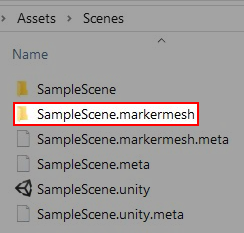
Fig.1. The Saved Directory Example
And the mesh files are named sequentially and stored in JSON format. For short, these mesh data are named markermesh below.
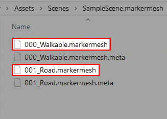
Fig.2. The Saved Markermesh Data Example
When a scene is loaded, nothing is changed to the scene in the hierarchy until you open the NavimeshMarker Editor Window via Window -> NavimeshMarkerWindow. Then, a gameobject named EditorOnly-WontSaved-MarkerMeshManager is added to the scene. The markermesh is loaded as sub-game objects with a MeshRenderer component attached to each of them, so the markermesh can be shown in the scene. The gameobject EditorOnly-WontSaved-MarkerMeshManager and the sub-objects are for editor only and won’t be saved in the scene. It means none of them will be included in the packed App. And it also means next time the scene is loaded in the editor, you have to open the NavimeshMarker Editor Window to show the markermesh in the Scene Window.
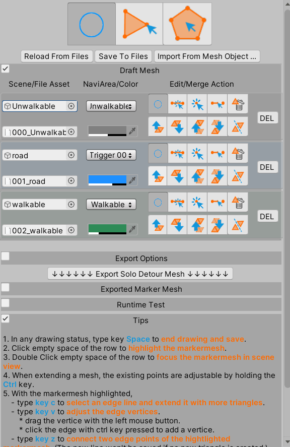
Fig.3. The Navimesh Marker Window
In the NavimeshMarker Editor Window, there are 2 buttons named Reload From Files and Save To Files. Automatically, the data is loaded when the window is shown and is saved when you complete the editing jobs or the scene is saved. Still, these jobs can be done manually via the 2 buttons. With another button named Import From Mesh Object…, a normal mesh can be imported from the asset or the scene.

Fig.4. The Serialization Buttons
The .markermesh files are in JSON format. And it is best to manage them with your revision control system(svn/git/…). Other than that, you don’t need to care about the storage too much, it has no impact on the scene data.
3. Edit A Markermesh
3.1. Freely Creation

Fig.5. The Markermesh Creation Button
By clicking the Markermesh Creation button, as shown above, you will start to mark a new area. The steps are as follows.
- Along the edge of the area, click on the scene view, a point is generated in the scene.
- Click the next point on one side of the area’s edge, a new line is got.
- Click the other side of the area’s edge, a new triangle is got.
- Repeat the upper step.
- Click the stop drawing button or type Esc key to stop and save.

Fig.6. The Stop Drawing Button
And some tips come as follows.
- The mesh needn’t be completed at one time. It can be extendable later as in Chapter 3.3.
- The mesh needn’t be accurate this time. The edge vertices can be adjusted as in Chapter 3.4.
- The mesh’s vertices do stick to the terrain. But still, the mesh can be partly unshown as the terrain is not plain and covers the mesh.
- Since nothing is filtered in the ray test, so the clicked point can be on a tree. It can be fixed by adjusting the edge point in the following chapter.
Here comes the video demonstration.
3.2. Regular Poly Creation

Fig.7. The Regular Poly Creation
By clicking the Regular Poly Creation button as shown above, you will start to create a new regular poly marked as Unwalkable area.

Fig.8. The Regular Poly Creation Parameters
Once you clicked the button, the parameters are shown. You can adjust the edges, the radius, and the rotation on the Y-axis.
Here comes the video demonstration.

Video 2. To Create A Regular Poly
3.3. Extension

Fig.9. The Extension Button
By clicking the Extension button as shown above, or type key c, you will start to extend an existing mesh.
- After the click, the nearest line to the mouse pointer will be highlighted.
- Please select one with the left mouse button.
- Then extend it to a triangle by moving the point.
- And click the left button to confirm it.
- Then move the mouse pointer as in Chapter 3.1.
Here comes the video demonstration.

Video 3. To Select An Edge Line To Continue
3.4. Edge Vertices Adjustment

Fig.10. The Edge Vertices Adjustment Button
By clicking the Edge Vertices Adjustment button as shown above or type key v, you will start to adjust the edge vertices slightly.
- After the click, all the edge vertices are highlighted.
- To move a vertice, please press the left mouse button pick one, then drag it and release it.
- To add more edge vertices, please hold key CTRL and click on the edge line.
Here comes the video demonstration.

Video 4. To Adjust Edge Vertices’ Position
3.5. Connect two edge points to form a new triangle.

Fig.11. The Connecting Edge Vertices Button
By clicking the Connecting Edge Vertices button as shown above, or type key z, you will start to connect two edge points of the highlighted mesh data.
- After the click, all the edge vertices are highlighted.
- To make a new line, please select one vertice and then the other. The line is only kept in the memory(can’t be saved) until it forms a triangle with the existing lines.

Video 5. To Connect Edge Vertices
3.6. Triangle Deletion

Fig.12. The Triangle Deletion Button
By clicking the Triangle Deletion button as shown above, or type key x, you will start to delete an existing triangle.
- As the mouse moves, the pointed triangle is highlighted.
- Please type key d to delete it.
4. Handle Multiple Markermeshes
4.1. Merging

Fig.13. The Merging and Splitting Buttons
By clicking the merge button, the markermesh will be merged to its upper/lower.
If the 2 markermeshes are not next to each other, please move them with the move button described in Chapter 4.2.
4.2. Splitting

Fig.14. The Movement Buttons
By clicking the split mesh data button, the markermesh will be split into several not connecting pieces.
If all the vertices of the mesh triangles are connected, nothing will happen.
4.3. video demonstration

Video 7. To Merge and Split Meshes
5. Detour Format Exportation.
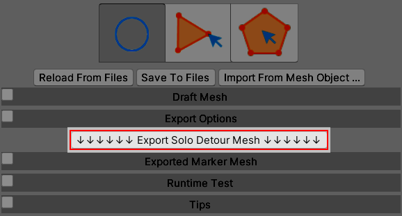
Fig.15. The Movement Buttons
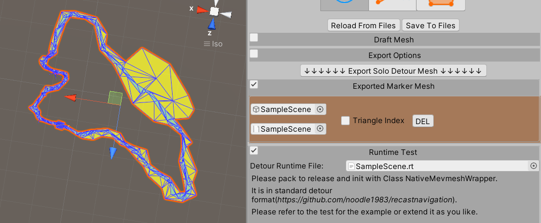
Fig.16. The Movement Buttons
Here comes the video demonstration.

Video 8. To Export Detour Mesh
6. Runtime Usage Example
After the exportation is completed, the detour runtime file is generated from the final mesh too.
The examples will show how to use the detour format data.
6.1. Runtime File
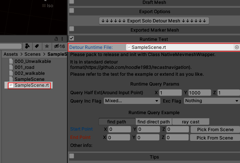
Fig.17. The Movement Buttons
6.2. Runtime Query Params
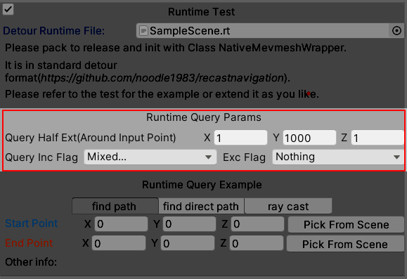
Fig.18. The Movement Buttons
You can adjust the parameters as above during the test. Please refer to the Recast Doc for the usages of the parameters.
6.3. Runtime Query Example
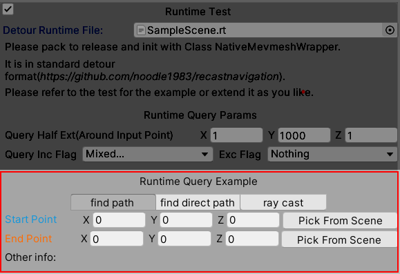
Fig.19. The Movement Buttons
There are 3 examples, which are find path, find direct path, and raycast. The find path will show the path from the start point to the endpoint. It may contain some mid-points which look not so straight. So the find direct path does more calculation basing on the find path to make it look more straight. Please refer to the video for how to set the start point and the endpoint.

Video 9. Runtime Query Example
7. Others
- The navigation cost of each area needs to be set at runtime.
1
2
3
//For the bake workflow
NavMesh.SetAreaCost((int)NavMeshType.Road, 1);
NavMesh.SetAreaCost((int)NavMeshType.Walkable, 10);
1 | auto navmesh = NativeNavmeshWrapper.NewInstance(detourBinPath); |
8. Support & Contact & When you think of it is better if… & Consultation
- email: noodle1983@126.com

